![]()
![]()
![]()
![]()
![]()
![]()
![]()
![]()
Order duplicate or replacement keys

![]()
![]()
|
Order duplicate or replacement keys
|
![]()
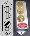
Key Flow Diagrams, Conventions & Key Interlock SchemesWhen formulating a key interlock system, we usually ask the customer to forward to us a single line diagram of the electrical scheme, illustrating all the switchgear involved. In addition to this, a tabulation of the switching scenarios and details/notes on disallowable actions should also be included. We then, in turn, take this single line and add key interlock symbols and notes according to the scheme arrived at. Figure "a" is an illustration of a key-interlocked breaker, the shaded angled rectangle contained within the circle indicates the interlock key is in the captive position and the breaker operable. The "LO"(lock open) beneath each symbol indicates the function of the interlock is to lock the breaker in the open position. Figure "b" indicates that the breaker is in the locked open position and the key is removed, hence the unshaded vertical rectangle contained within the circle.
The above symbols are generic key interlock representations, when the final system hardware becomes specified, the representation becomes a miniature graphic of the actual interlock style specified. Below are shown symbols congruous to those above indicating the use of a B-4003-1 (flat mounting) key interlock.
The key flow diagram is normally shown with the equipment in its normal operating configuration. Keys are represented flowing in the direction required for a switching change from the initial condition. Most OEM's when formulating their own key flow diagrams use symbols/graphics similar to those shown. Other key interlock functions include "LC" (lock closed) and "LOC" (lock open or closed). When the keys are non-removable they may be referred to as trapped, retained or captive etc., when they are removable they may be referred to as free, released, etc. Some other common key flow diagram graphics:
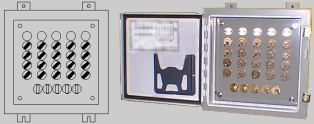
In addition to single and multi key units, dual combinated key interlocks are useful in many key sequences. This unit is able to accept and be operated by one of two independent keys at any time and is represented below. Key transfer interlocks are devices used for the exchange of keys. When one or several keys is inserted and trapped, one or several keys become releasable. Such units can be applied to various situations, i.e. where several keys are required to access enclosures or the physical mounting limitations on equipment does not allow the use of multi-key interlocks. Examples of key transfer interlocks shown below are a B-1088-3, 1/2 grouping and a B-1088-25, 5/20 grouping.
|
![]() Home
Home
![]() Products
Products
![]() Schemes
Schemes
![]() Info
Info
![]() Forms
Forms
![]() Contact
Contact
![]() Site Map
Site Map
![]() EMail
EMail
© 2002 Superior Interlock Corporation [All rights reserved]
Phone: (718) 821-8949